The first time a developer buys a utility-scale battery storage system, the proposals from three different vendors look unrecognisably different. One quotes a "fully integrated BESS solution." Another itemises BMS, PCS, and EMS as separate line items. A third bundles everything into a containerised product but lists ten optional add-ons that turn out to be the things you actually need. The acronyms — BMS, PCS, EMS, TMS, SCADA, PCC, PPC — start to blur. The warranty terms reference standards nobody on the procurement team has read. By week three, the developer is making a multi-million-euro decision against a vocabulary they had no time to learn properly.
This guide unpacks the four components that make up a utility-scale battery storage system — what each one actually does, how to spec each one independently, the warranty traps that catch first-time buyers, and which layer determines whether the BESS stacks revenue across aFRR, FCR, and arbitrage — or just sits there waiting for instructions. Written for BESS developers, EPCs, asset managers, and IPPs making their first or second utility-scale storage procurement.
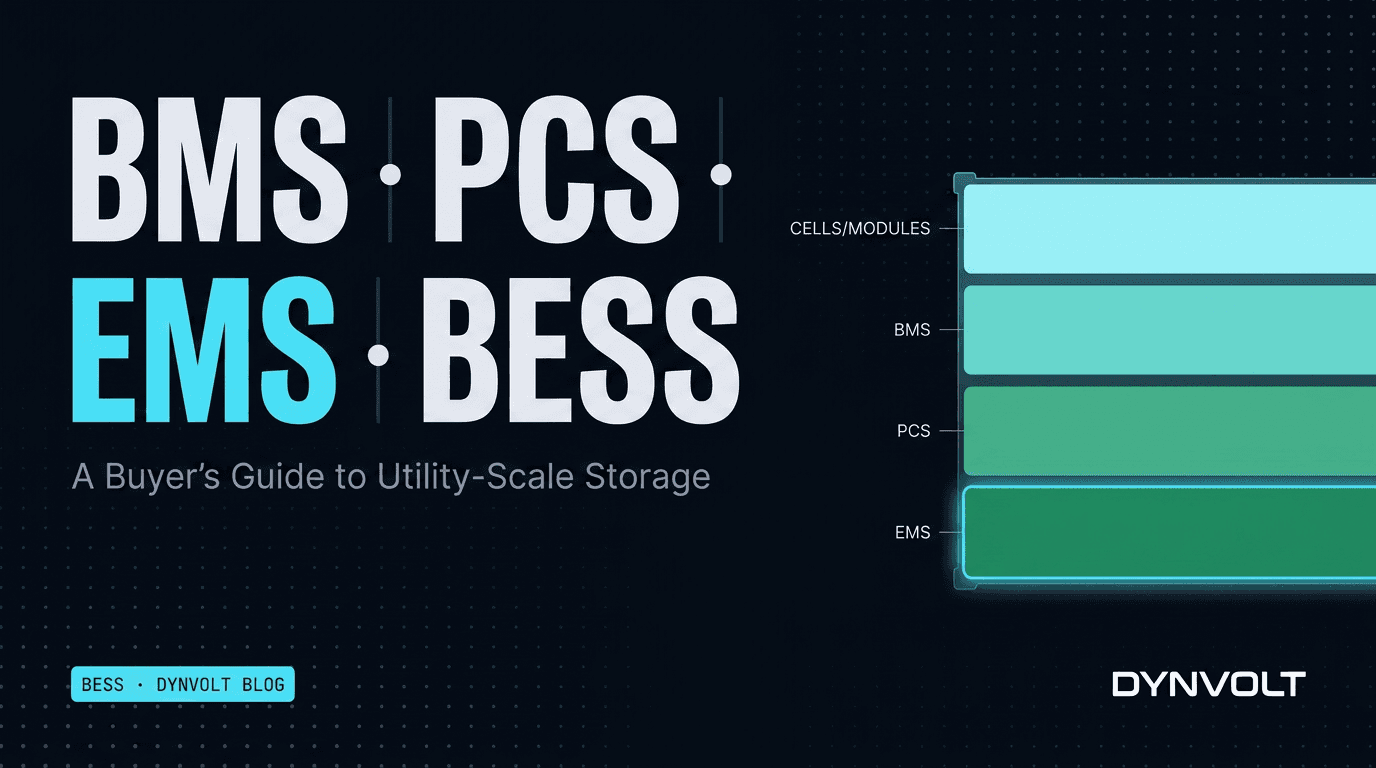
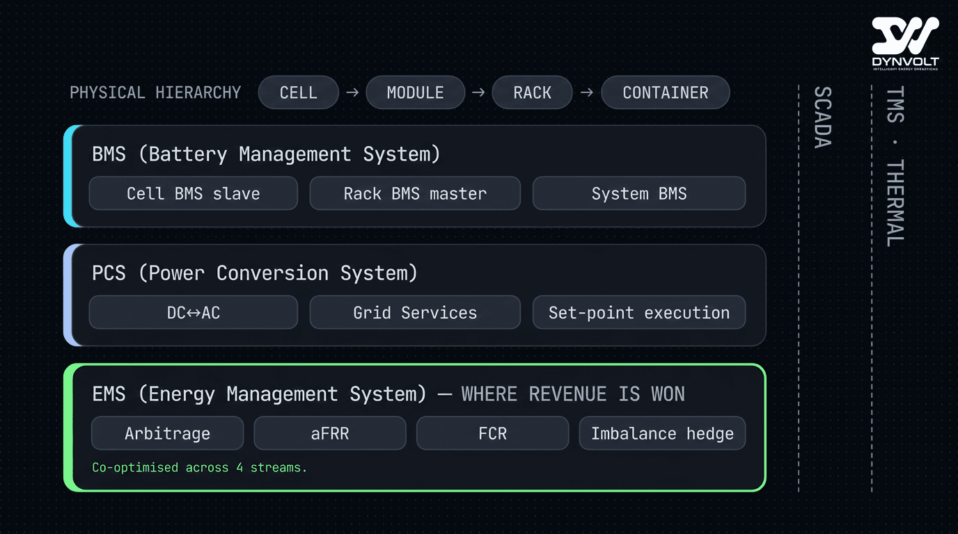
- A utility-scale BESS is four stacked layers — cells/modules/racks → BMS → PCS → EMS — with SCADA and thermal management spanning across.
- The BMS protects the cells. The PCS converts DC↔AC and provides grid services. The EMS decides what the system does with its energy.
- The EMS is where revenue is won or lost — the same hardware can produce substantially different returns depending on whether the dispatch layer is naive or co-optimised.
- Grid-forming inverters (PCS) are required for stand-alone or weak-grid sites; grid-following inverters are sufficient for strong-grid arbitrage applications.
- Single-vendor 'integrated' BESS systems are easier to buy but lock you into one EMS strategy — multi-vendor stacks let you pick best-of-breed at each layer.
- Warranty envelopes (cycle count, depth-of-discharge bounds, thermal limits) are set by the cell manufacturer and propagated through the BMS — exceeding them voids the warranty entirely, not partially.
The Anatomy: Cells, Modules, Racks, Containers
Before the acronyms, the physical hierarchy:
- Cell — the elementary lithium-ion electrochemical unit. Modern utility BESS uses prismatic LFP (lithium iron phosphate) cells almost exclusively for safety and cycle life.
- Module — a stack of ~12–24 cells in series with monitoring electronics and a heat plate. Modules are the field-replaceable unit.
- Rack — a vertical stack of modules with a rack-level BMS slave and DC bus. Typically 50–250 kWh per rack.
- Container — an ISO-format enclosure (often 20-ft or 40-ft) housing multiple racks, the PCS, the TMS, fire suppression, and access for service. Typically 2–6 MWh per container.
The BMS, PCS, and EMS are the active electronics. Everything else is plumbing.
What Each Layer Actually Does
BMS — Battery Management System
The BMS is the embedded controller that keeps the cells alive. It runs at three hierarchical levels in a utility BESS:
- Cell-level BMS slave — per-module hardware that measures each cell's voltage, temperature, and balance state, multiple times per second
- Rack-level BMS master — aggregates the cell data from all modules in the rack, performs active or passive cell balancing, runs the safety interlocks
- String-level / system-level BMS — coordinates multiple racks, maintains the system-wide State-of-Charge (SoC) and State-of-Health (SoH) calculation, talks to the PCS to enforce charge/discharge limits
The BMS owns the safety envelope. If a cell temperature exceeds threshold, the BMS opens the rack contactor and isolates the bank. If a cell voltage approaches the upper or lower safety limit, the BMS reduces or refuses the charge/discharge command. The PCS and EMS cannot override the BMS — and any architecture where they appear to be able to is a critical safety flaw.
What the BMS protects:
- Over-voltage (cell-level and rack-level)
- Under-voltage (deep discharge damage)
- Over-temperature (thermal runaway precursor)
- Over-current (per-rack and per-string)
- Cell imbalance (long-term degradation)
- Ground faults (insulation resistance monitoring)
PCS — Power Conversion System
The PCS is the bidirectional inverter that converts DC from the battery to AC on the grid side and back. For utility BESS, the PCS is typically a containerised three-phase unit at 1–4 MW per inverter, with multiple inverters per BESS container.
The PCS does three jobs:
- DC↔AC conversion at high efficiency (97–99% round-trip on modern silicon-carbide units)
- Grid services execution — frequency response, voltage support, ride-through during disturbances, ramp-rate control
- Set-point execution — receives active and reactive power set-points from the EMS or a higher-level controller and executes them within the BMS-defined safety envelope
The single most important PCS spec for ancillary services participation is response time — how fast the PCS can move from one power set-point to another in response to a TSO command. For aFRR participation, the requirement is typically 100% of the activated reserve within 7.5 minutes (slow aFRR) or 30 seconds (fast aFRR). For FCR, the requirement is full activation within 30 seconds for a 200 mHz frequency deviation. Modern utility PCS units respond to set-point changes within tens of milliseconds, well inside any TSO requirement.
Two PCS sub-classes worth distinguishing:
- Grid-following (GFL) inverters synchronise to the grid voltage waveform. Cheaper, mature technology. Will trip and disconnect if the grid voltage collapses (no black-start capability).
- Grid-forming (GFM) inverters can establish a grid voltage waveform independently. More expensive, newer technology. Required for stand-alone (off-grid or microgrid) applications and increasingly required by TSOs for new BESS connections in weak-grid areas.
For a typical strong-grid utility BESS doing arbitrage and aFRR, GFL is sufficient. For weak-grid sites, island-capable sites, or sites where the TSO mandates grid-forming for fault-current contribution, GFM is required.
EMS — Energy Management System
The EMS is the software layer that decides what the BESS does. Charge now? Discharge now? Bid into aFRR? Reserve capacity for tomorrow's arbitrage window? These are EMS decisions.
The EMS sits above the PCS in the control hierarchy and below the SCADA / market-facing trading layer. Its inputs:
- Real-time SoC and SoH from the BMS
- Real-time grid frequency, voltage, power flow from the PCS or the point of common coupling (PCC)
- Market data — current day-ahead clearing prices, intraday continuous order book, ancillary service activation signals
- Price forecasts for the next 24–168 hours
- Co-located generation forecast (for PV+BESS hybrids)
- Constraint inputs from the asset owner — cycle limits, depth-of-discharge bounds, thermal caps, must-charge windows for warranty maintenance
The EMS outputs power set-points for the PCS, refreshed at whatever cadence the strategy requires — every 15 minutes for arbitrage, every second for FCR, sub-second for inertial response (where the BESS is grid-forming).
This is where revenue is won or lost. The same battery hardware running a naive arbitrage-only EMS versus a properly co-optimised EMS that stacks revenues across day-ahead, intraday, aFRR, and FCR can produce substantially different annual returns. The hardware is largely commoditised at the top tier; the dispatch logic — the BESS optimization layer — is where the differentiation lives.
SCADA, Site Controller, and TMS — the spanning layers
Three more components round out the stack:
- SCADA — supervisory control and data acquisition layer. Polls every device (BMS, PCS, meters, weather station, fire panel), normalises the data into a single time-series schema, and exposes it to operators and the cloud control plane.
- Site controller / PPC (Power Plant Controller) — enforces site-level grid-code constraints (active power limit, reactive power profile, ramp rate) regardless of what the EMS wants. The PPC is the safety layer that sits between the EMS's wishes and the PCS's execution.
- TMS (Thermal Management System) — keeps the cells within their warranty thermal envelope. Liquid-cooled in modern utility containers; HVAC-based in older designs. Often integrated into the container manufacturer's offering.
The Procurement Checklist Per Layer
What to actually ask for and verify per layer, in a procurement RFP:
For the BMS
- Cell chemistry, capacity per cell, voltage range
- BMS slave / master / system hierarchy clearly drawn
- Cell-level monitoring resolution (mV, °C, sampling rate)
- Active vs passive cell balancing
- SoC algorithm — Coulomb counting, OCV correction frequency, drift rate
- SoH calculation methodology
- Communication protocol to the PCS and EMS (CAN bus, Modbus TCP, OPC-UA, etc.)
- Safety interlock independence — verify the BMS can act on its own without external command
- Fault and warning enumeration — written into the FAT (factory acceptance test) plan
For the PCS
- Rated AC power (MW) at the cabinet output
- Round-trip efficiency at typical operating points (not just peak)
- Response time to set-point change
- Grid-forming vs grid-following declaration
- Low-voltage and high-voltage ride-through curves vs grid code
- Reactive power capability (Q vs P curve at PCC)
- aFRR / FCR certification and TSO accreditation track record
- Communication protocol to the EMS and PCC
For the EMS
- Supported revenue streams (arbitrage / aFRR / FCR / imbalance / capacity market / DSR — most platforms support some subset)
- Co-optimisation approach — does it stack revenues across multiple streams, or schedule them in sequence?
- Cycle-cost modelling — does the dispatcher account for cell degradation as a real cost?
- Warranty envelope enforcement — can the asset owner set hard bounds the EMS will never violate?
- Forecast inputs supported — own forecast, third-party feed, market price feed
- Re-optimisation cadence
- Integration with the trading desk — direct nomination submission, manual approval, hybrid?
- Audit trail — every dispatch decision logged with the price and forecast that drove it?
For SCADA / PPC / TMS
- Real-time telemetry resolution at the BMS, PCS, and environmental layers
- Local data buffer for comms-loss survival
- PPC enforcement of grid-code constraints — written verification it cannot be over-ridden by the EMS
- TMS coolant temperature setpoints aligned to the cell warranty thermal window
- Fire detection and suppression integration with the site controller
Vendor Classes
The market structures into three loose tiers:
Tier 1 — Integrated single-vendor BESS
Sungrow, Huawei, BYD, CATL, Tesla Megapack. These vendors ship a turnkey container with their own cells, BMS, PCS, EMS, and TMS, all factory-integrated.
- Pros: single throat to choke for warranty, single FAT, one set of comms protocols, fast deployment
- Cons: locked into that vendor's EMS strategy — usually adequate for arbitrage but rarely best-in-class for ancillary stacking — and locked into their cell roadmap
Best fit: developers shipping their first 1–3 BESS sites who need speed-over-flexibility.
Tier 2 — Cell + container from one vendor, PCS from another, EMS from a third
CATL or BYD cells in a container from Powin or Wartsila, PCS from Power Electronics or Sungrow, EMS from a specialist (FlexGen, Wartsila GEMS, DYNVOLT, EnergyHub, etc.). The integrator stitches it together.
- Pros: best-of-breed at each layer, EMS flexibility, easier to swap components later
- Cons: more procurement work, multiple warranty contracts, integrator margin
Best fit: developers building a fleet who want long-term flexibility and revenue optimisation.
Tier 3 — Full custom stack
Cells, modules, racks, BMS, PCS, EMS, SCADA all separately procured and integrated either in-house or through a system integrator. Rare outside of very large utility-scale projects (>200 MWh) and research installations.
Warranty Traps That Catch First-Time Buyers
The cell manufacturer's warranty is the single most expensive document in the BESS procurement file. The traps:
- Cycle count limit — typically expressed as N cycles at X% DoD at Y°C. Exceeding the cycle count voids the warranty entirely. The EMS must count cycles correctly (a cycle from 80% to 20% is one cycle; a partial cycle from 80% to 60% is partial).
- Depth-of-discharge bounds — most warranties exclude operation below a minimum SoC (often 5–10%) and above a maximum (often 95–98%). Operating outside the band voids warranty.
- Thermal limit — sustained operation above the warranty cell temperature voids warranty. The TMS must keep up; the BMS must throttle when it can't.
- Calendar age vs cycle age — most warranties cover whichever comes first. A BESS that sits idle still ages calendrically.
- Augmentation requirements — some warranties require the system to maintain a specific energy capacity over its life via cell replacement. The augmentation cost is the BESS owner's, not the manufacturer's.
- Grid-event exclusions — many warranties exclude damage from grid faults the system was designed to ride through. Read the ride-through clauses carefully.
The EMS that respects all of these is doing real work. The EMS that doesn't is generating revenue today and a warranty claim refusal tomorrow.
Revenue Stacking: What Each Component Enables
The four common BESS revenue streams in European markets:
| Stream | Time horizon | Hardware requirement | EMS capability needed |
|---|---|---|---|
| Day-ahead arbitrage | Hours | Standard PCS, basic EMS | Price forecasting, daily optimisation |
| Intraday continuous | 15 min | Standard PCS, faster EMS | Real-time price feed, intraday execution |
| aFRR (frequency restoration reserve) | 30 s – 7.5 min | aFRR-certified PCS, fast set-point response | Capacity reservation, activation signal handling |
| FCR (frequency containment reserve) | < 30 s | FCR-certified PCS, autonomous response | Symmetric capacity reservation, droop control |
| Imbalance hedging | 15 min | Standard PCS | Co-located forecast access, post-DAM optimisation |
A BESS doing only arbitrage uses one stream. A BESS co-optimised across arbitrage + aFRR + FCR + imbalance uses four — but the same battery can only sell its capacity to one stream at a time. The art of the co-optimised EMS is scheduling each MW-hour to its highest-value stream window without violating cycle budgets.
Frequently Asked Questions
Conclusion
A utility-scale BESS is four stacked layers, each with its own specification, vendor class, and failure modes. The buyer who treats it as a single product gets locked into one set of trade-offs. The buyer who treats it as four independent layers can spec each one against the actual mission — and gets a system that produces materially more revenue across its full warranty life.
DYNVOLT's BESS optimization module covers the EMS layer for both stand-alone and PV-co-located storage, with cycle-cost-aware dispatch, warranty-envelope enforcement, and revenue stacking across day-ahead, intraday, aFRR, and FCR. See the BESS module for the architecture, the architecture brief for the integration story, or request a 14-day pilot on your site.